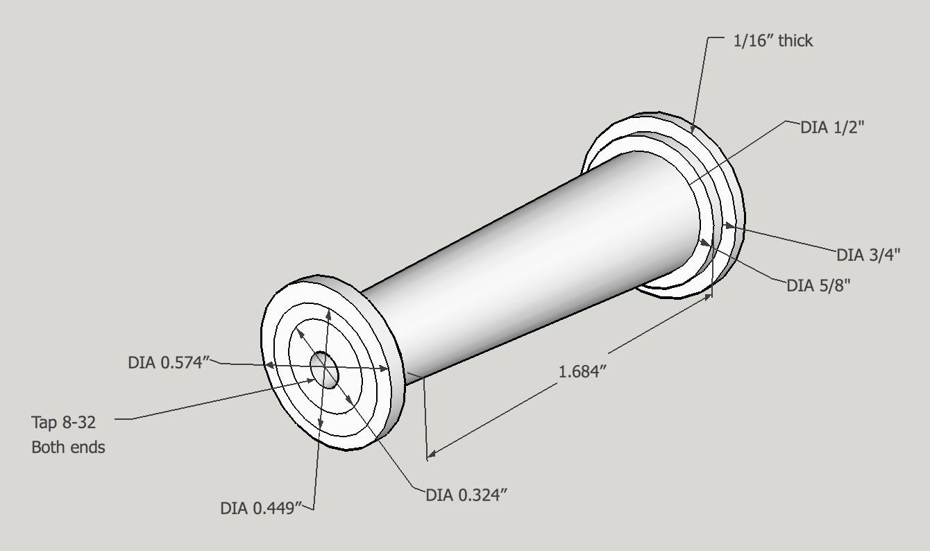
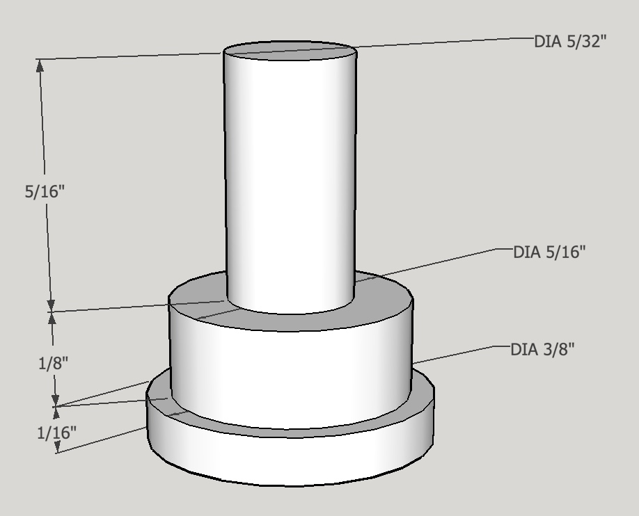
The columns to support the top and bottom frames were designed next. A classical tapered cylinder was selected for both ease of construction and elegant look. Special screws will anchor the columns and serve as feet/caps for the columns. A 3° taper seemed about right in the SketchUp design phase. Two 1/16" rings will finish both the bottom and top of the columns. Both ends will be tapped 8-32 (1/4" deep) to receive the special screws through the frames. The overall length of the column needs to match the height of the gear stacks. This is 1.934". The tapered length is then four 1/16" rings shorter or 1.684" long. About 0.032" should be added to this length for a fudge factor as the top gear stack washers don't need to touch the top frame. A sketch is shown below.
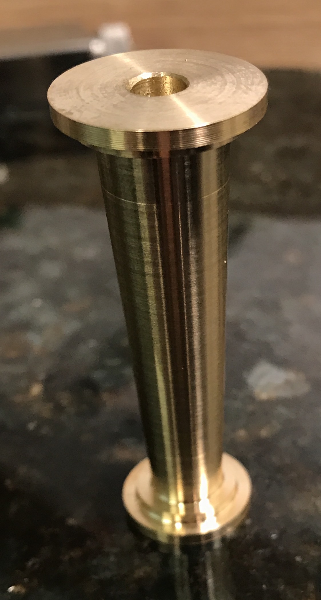
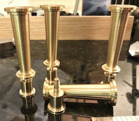
A 2.5" length of 3/4" brass hex was faced on both ends and drilled (#29) and tapped. One end was selected as the stub end and this end was countersunk (#8) 1/2" before drilling and tapping 8-36. (Switched to 8-36 relative to 8-32 because a bottoming tap is available in my collection.) The hex was then reduced to 3/4" round for 2". This was further reduced to 5/8" with a right hand bit leaving 1/4" unreduced near the chuck. This left an angled finish on the right end to be cleaned up later. Again this was reduced to 1/2" leaving the second 1/16" step on the chuck end. The right end was then reduced with a Left hand bit to 0.574", 0.449", and 0.324" leaving two steps and setting up the small dimension for the taper. The Sherline headstock was rotated 3° by eye. (Checking with a dial test indicator showed a difference of 0.005" per 1" of travel from calculated.) Most of the taper was made using the left hand cutting tool leaving only a little to clean up with the right hand tool near the chuck. The column was parted off and is shown in the photo below. This process was repeated 3 more times to produce four columns.
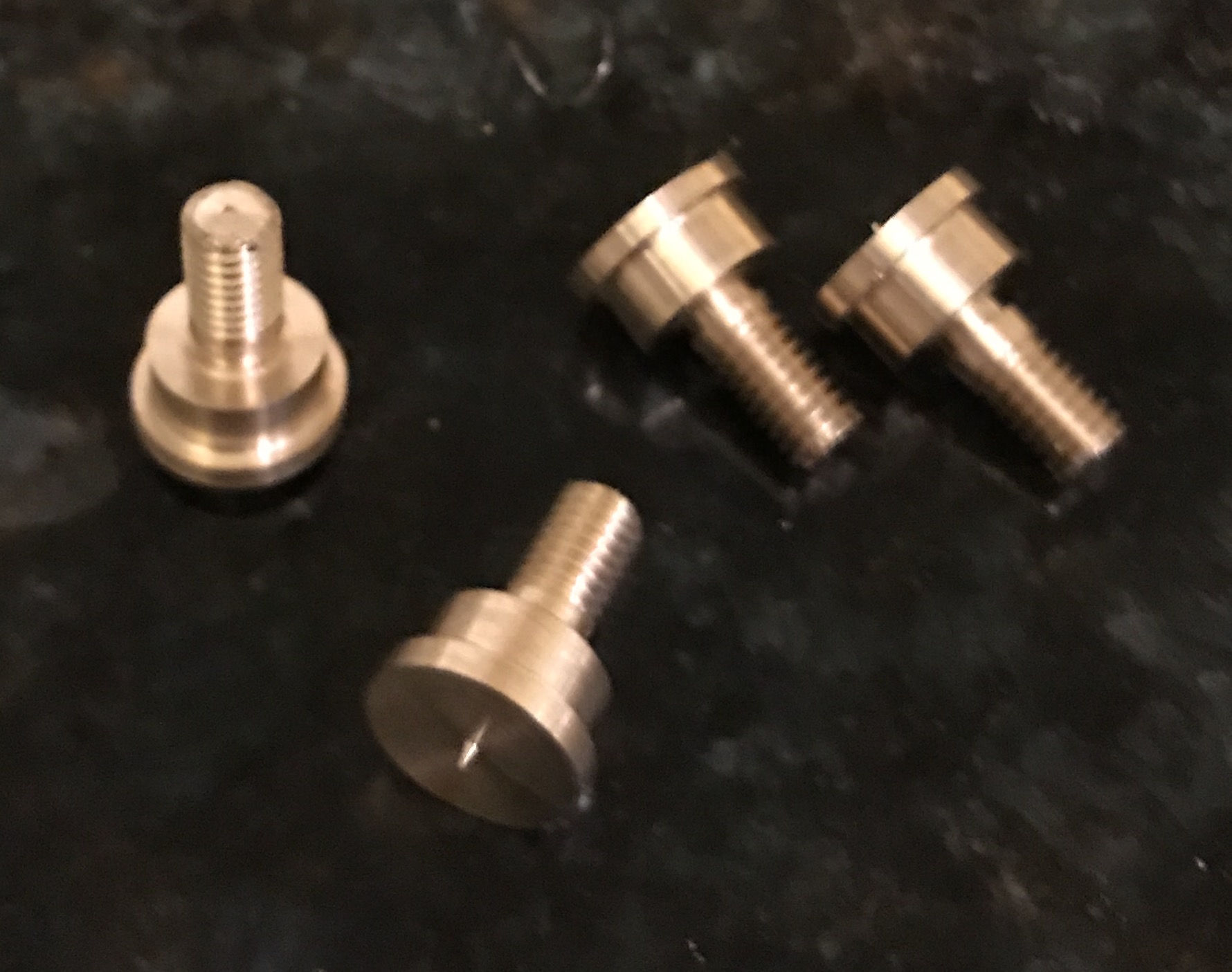
The screws for the bottoms were made next. They are 1/2" long plus the threaded section as shown in the following picture.
A 2 1/4" length of 1/2" brass round was cut with a hacksaw and faced on one end. A 1" length of the rod was cleaned up so the diameter was slightly less than 1/2". The rod was turned down to 3/8" for a length of 0.845". 0.407" at the tailstock end was then turned down further to 0.164". The corners were chamfered and 8-36 threads were cut with a die. for most of the length of the narrow end. The foot-screw was parted off at 0.907". A second foot-screw was made from this same piece of stock in a similar fashion. Two more foot-screws were made as well. All four are shown in the following photograph.
One of the columns did not have a deep enough hole for the foot screws. One of the foot screws was shortened with a hacksaw about 1/16" for a tight fit on this column through the dodecagon.
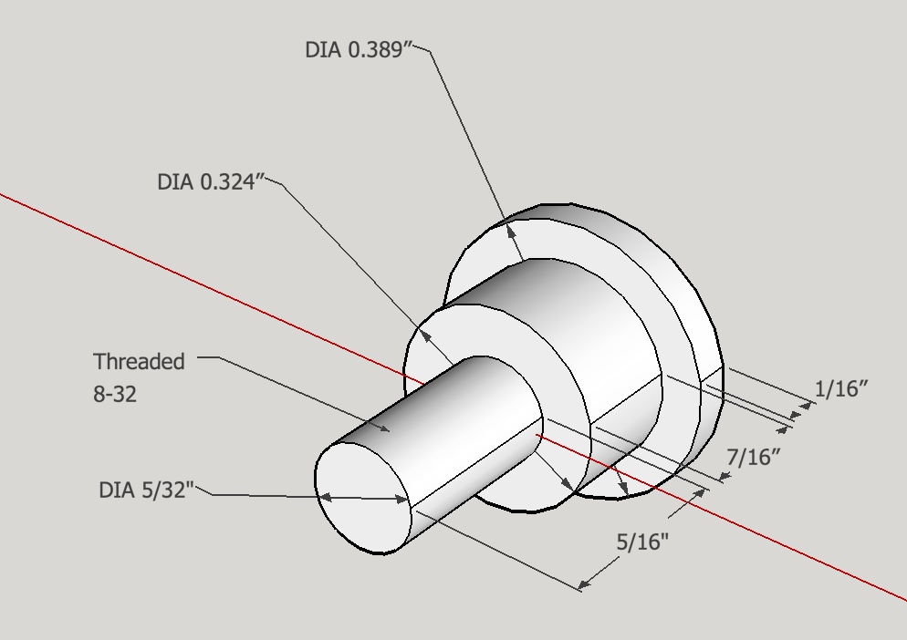
Four caps were made for the columns from 3/8" brass rod. A 3" length of rod was held in a three jaw chuck with about 5/8" extended. This was faced and then cleaned up on the outside with a 0.005" cut. A length of 0.432" was reduced to 5/16" and a length of 0.312" reduced to 0.162" (slightly smaller than standard 0.164") for threading. The rounded corner where this 0.162" meets the face was removed with a parting tool so the cap would sit flat. It was also slightly undercut though this was not needed. The end was slightly chamfered with a file. The 5/16" length of brass rod was threaded 8-36 with a die in the tailstock die holder. The part was then parted off at 0.50". This sequence was repeated to produce three more caps.